Linear Pump Operating Principle
 The Linear-motor-driven Free Piston System (Pat.) has an internal piston inside the cylinder which is driven by an electro-magnet and spring system controlled by the alternating input current cycle. The piston thus forms a single combined structure of two usually different devices; motor and pump.
The system is quiet and vibration free, and offers the advantages of easy maintenance and a long operating life.
Click here to download a comparison between Nitto Kohki Linear shuttle pumps and older style diaphragm pumps in Adobe PDF format.
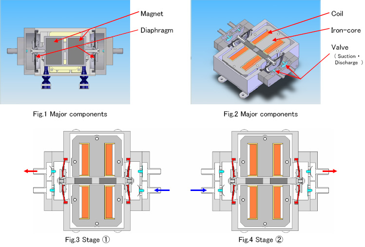
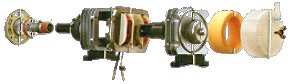
Principle of linear piston pump
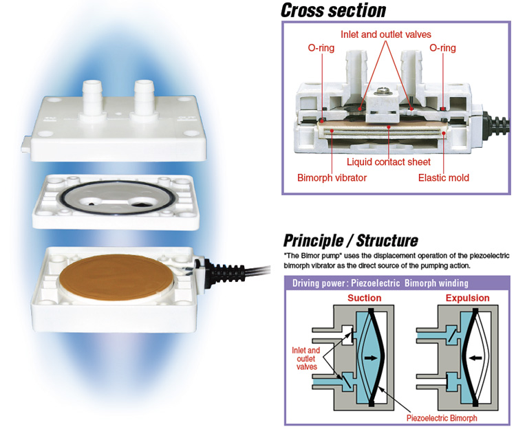
 The activated electro-magnet attracts the piston against the return spring, while air is taken into the cylinder through the opened inlet valve.
When the electro-magnet is deactivated, the return spring pushes the piston back, and the compressed air is brought out of the cylinder through the now open outlet valve.
The activated electro-magnet attracts the piston against the return spring, while air is taken into the cylinder through the opened inlet valve.
When the electro-magnet is deactivated, the return spring pushes the piston back, and the compressed air is brought out of the cylinder through the now open outlet valve.
The system can function as either an air compressor or as a vacuum pump.
Fewer Components
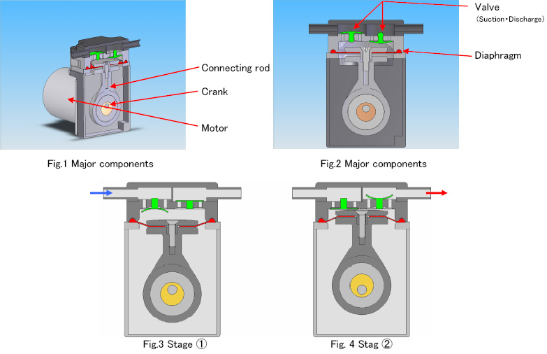
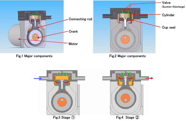
 The pump's unique and simple structure has no complicated transmission mechanism such as a crankshaft, connecting rods, ball bearings, etc., which are widely used in between the motor and compressor in conventional pumps.
 Easy Maintenance
Replacement of the piston is easily achieved by simply removing the end cap connected to the pump housing by unscrewing the four screws which hold the cap in place. Completely oil free construction is achieved by the combination of smooth Teflon® seals with superior resistance against abrasion on sliding piston surfaces and the "air bearing effect" created by the unique air path design.
Features of the Linear-motor-driven Free Piston System
- Self-cooling design Cool intake air is blown onto the electro-magnetic coils through an orifice, making sealed construction possible and preventing the escape of operating noise.
- Low noise level The machine has no complex transmission system. This results in the lowest noise level possible due to the absence of rotating parts or ball bearings. Operating noise is also quelled due to the pump's sealed configuration.
- Small output air pulsation Piston reciprocation is synchronised with input power frequency regardless of load (i.e.; 3000 rpm for 50Hz and 3600 rpm for 60Hz). Such high RPM adversely reduces each discharge volume and eliminates any problems caused by pulsation.
- Low Power Consumption The piston is the only component in the system which moves. The absence of transmission usage to pass the power to the piston means that there is a large reduction in energy loss, and an improvement in efficiency over other pumps.
- Compact composite structure This unique system enables direct reciprocation of a single part which consists of composite piston and armature. The incredibly compact and lightweight design was achieved by combining what are two different functions in other pumps - motor and piston - into a single structure.
- Anti-overpressure mechanism When the output pressure exceeds the rated value the piston stroke will automatically diminish and prevent over-pressurising. At the same time, the current and power consumption will also be automatically reduced, thus eliminating possible failure caused by tentative overload.
- Low vibration The aluminium die-cast piston produces very little vibration or kick-backs. Little or no damage from vibration stress is therefore sustained during operation. Even secondary vibrations are absorbed by special soft rubber feet.
- Quick Response Due to the lower starting current, the unit can immediately respond to frequent on-off input signals, even under back pressure conditions.
- Longer Durability Oil free construction requires no periodical oil-up. This simple mechanism has the fewest number of moving parts possible. Long and stable performance is assured.